Recycled Rocketry
Rocket motor casings with integral aluminum nozzles
Foundry
Micro
Mini
Midi
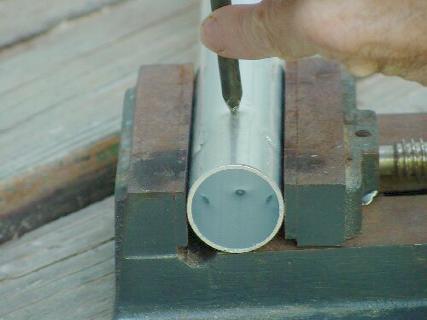
Dimples
Flight Test
How To...
Home
| How To...
|
Recycled RocketryRocket motor casings with integral aluminum nozzles |
Foundry |
Molten aluminum is poured into the void between the cones to create a nozzle. The diverging cone is removed, and the nozzle throat is then drilled to the desired size with an ordinary bit. The lower plug and steel cone are pressed out with a dowel.
The result is an aluminum nozzle, integral with the tubing, having both converging and diverging cones of any desired angle, and a throat of any desired diameter.
The steps
1. Acquire some aluminum tubing. I have used a range of sizes, the most satisfactory so far has been the largest, "1-1/4 inch" outside diameter (actually 1.2 inch, roughly 30mm) and 1.1 inch inside diameter. This was purchased at a local hardware store
![]()
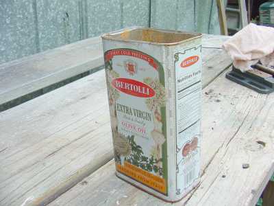
2. Arrange for melting some scrap aluminum. I use a simple charcoal foundry, melting the aluminum in steel cans with the help of a vacuum cleaner. There are a few photos below, more detail on the Foundry page.
3. Make a steep diverging cone former from thin sheet steel, such
as that cut from a food can.
Skinny pliers are very helpful, and leather
gloves reduce the number of band-aids required.
I find that the steepest cone I can manage
happens to have about a 12 degree half-angle.


4. Also make a converging cone the diameter of your tubing.
![]()
You math types will laugh, but please recall that my degree is in psychology. So I spent some time playing Euclid, trying to figure out the formula by which to cut the blank to make a cone with a 60 degree vertex, thus 30 degree half-angle. Finally it dawned on me: Cut a disk twice the diameter of the motor tube. Cut it in half. Roll it into a cone. Duh.
5. Pack a wad of aluminum foil tightly into an existing converging cone. I started by using the steel nozzle Foy sent me last year. This requires a second flat plug to hold the converger upright in the tube.
Since then I have created a "demonstrator" nozzle in a short piece of tubing, which works even better. Ram the aluminum foil wad with a dowel and hammer until it is compressed into a solid slug. The slug must be tight enough that it will stay in place when the melted aluminum is poured onto it, and loose enough that it can be moved through the tube with moderate pressure.


Yeah, that last cone is a bit steep. I will use it anyway.
6. Cut a piece of tubing for the engine. It should be an inch or so longer than you want the finished case to measure, as some of it will be cut off after casting.
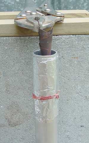
7. Decide which end should be the nozzle, and wrap the last four inches with 20 layers or so of heavy-duty aluminum foil. Secure it with a twist-tie, or perhaps a sleeve of tin-can metal.
8. Place the steel converging cone on top of the aluminum foil cone, insert it in your engine tubing, and move it up until it is about 3 inches from the nozzle end of the tube. The inner steel cone is not essential: I have made several nozzles using the foil cone alone, and they work fine. But the steel covering makes for a smoother cone and facilitates removal of the foil plug.
9. Clamp the tube in a vise or any contraption that will hold the nozzle-end up.
10. Arrange a stand and some clamps to hold the diverging cone just inside the nozzle-end of the tube. Center it well, and clamp it firmly. Be sure to leave a bit of space to pour in the molten aluminum.
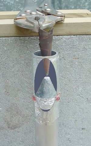
Here is the big picture:
 Setup for casting
 |
1. Aluminum Tubing
2. Tightly compressed aluminum foil wadding. This supports the convergence former and prevents molten aluminum from leaking past. 3. Convergence former, steel sheet-metal cone, cut from tin can. This cone is not required - a well-made foil plug will suffice, but the steel cone gives a smoother finish. 4. Divergence former, steel sheet metal cone, 15 degree (supported from above by clamps) 5. Opening. Gap between aluminum tube and divergence former. Pour molten aluminum in here. Before you pour: Wrap the nozzle-end of the tubing tightly with 16 to 20 layers of heavy-duty aluminum foil, and secure it with a twist-tie or something. This helps prevent melting of the tubing wall. |
 |
 |
Here is an alternative I have just started testing. The divergence former sticks nicely in the aluminum plug. This may allow better centering. The first attempt failed, but it was because I got too generous with the hot aluminum.
11. Fire up the little foundry, and heat some aluminum until it melts and glows dull red.


12. Pour this molten aluminum into the gap between the diverging cone and the aluminum tube. Fill up the gap, but don't overflow it. If you don't get it quite full on the first pour, resist the urge to add more. The tubing wall has often collapsed when I have tried to "top it off," or when the aluminum runs over the edge and flows down the side, melting a wide gap.


Notice the smooth texture of the tube before molding the nozzle (first photo), and the rough texture afterward (third photo). I do not understand this effect, but it is useful here: Apparently the AL tube partially melts but doesn't collapse (usually!) When this happens, the nozzle is bonded to the tubing very nicely, and the dimpling is not needed.

The cast end is usually very rough, so I cut if off with a chop-saw, then grind or sand the end to make it pretty.
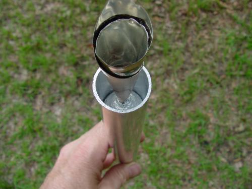
13. Let it cool, remove the divergence cone, then drill through the isthmus between the two cones. Just mount the tube in a drill press vise and use whatever size drill bit you want the throat to be. I am sure this could be done with a hand drill in a pinch, or even to press the two forming cones together so that the throat is cast-in.
In that last picture, the nozzle is not well sealed. Notice the gap between it and the tubing wall. That is why I cut it off and re-cast it. But first I took a picture because it shows how the converging cone shapes up. Nice and smooth, except for the ridge where the steel cone overlapped itself.
14a. Solid header. You might wonder how the other end of the tube is sealed. Well, it's pretty crude, but I cast plugs of aluminum in a short section of tubing, and glue them in with epoxy. A flat plug of aluminum foil is pounded into the bottom, and the tubing wrapped with wet paper toweling. The molten aluminum is allowed to cool until it will starts to lose its glow and begins to cling to the can, then it is poured. This makes for a loose fitting plug, which can be driven out of the tubing.
A hole is drilled and tapped in one end. After firing, the plug is extracted by driving in a small screw, heating the tube gently with a propane torch until the epoxy softens, then pulling the plug out with pliers.
14b. Propellant header. For a burn-through ejection initiator with tracking smoke, I often make a cylindrical plug of propellant which is catalyzed with 1% Fe2O3. The catalyst helps to prevent the header from going out when the pressure drops as main charge burns out. It is glued-in with epoxy, with a small hole exposing the top of the header to the ejection charge.

Remember that this header adds an end-burner to whatever grain is in
the case, increasing the Kn ratio a little.
Also note that the first part of the header will burn very fast while
exposed to the pressure of the burning propellant grain. When the
grain burns out, the header will slow to its 1-atmosphere burn rate.
A couple of my test engines "ejected" too quickly when I forgot about the
pressure-burn.
Remnants of epoxy can be removed by heating the tube, and wiping it
out with a brush or a stick wrapped with paper toweling.
The last little bit of glue is sanded out before reloading the casing.
I suspect that my failure to do this caused a couple of blown headers.


Please send any comments, questions, suggestions, or rude remarks to:
Jimmy Yawn
jyawn@sfcc.net
Back to Recrystallized Rocketry
7/7/02