
(This page is not yet finished! Please check back for more...)
The molds:
Individual grain molds are made by cutting 1-1/4 inch Schedule 40 PVC pipe into short sections 2-1/8 inches long. The ends are trued and sanded smooth, yielding a finished length of 2.1 inches.
A hole-saw is used to cut a plug of 1/4 inch plywood for the bottom of each mold. They are a little large and rough coming out of my hole-saw, and so are sanded to a loose fit. One side of the disk is covered with clear plastic adhesive tape, to keep the hot propellant from sticking to it.
A section of 3/8 inch hardwood dowel is cut 5 inches long, sanded, and the ends tapered a bit. The 1/4 inch hole in the middle of each disk is enlarged to make a semi-loose fit on the end of a 3/8 inch dowel.
Two strips of manila-folder paper are cut 1-7/8 inches wide. The last four inches of one strip is covered with clear plastic tape, again to prevent the propellant from sticking. These two strips are rolled up, inserted into the tube, and expanded to fit the wall, making sure that the taped surface is on the inside. More or less paper may be used to adjust the grain diameter.
A dowel is inserted into one of the plywood disks, and the unit inserted into one of the paper-lined tubes. The mold is now ready to accept the propellant...

...which has been heating in the toaster-oven (NOT a microwave oven!)
Rcandy keeps very well in these handy PVC containers, just a short section
of tubing with a slip-fit cap on either end. For insurance, I wrap it
in plastic wrap so it will survive a deluge. Or summer in Florida.


Filling the molds
A chunk of propellant is removed, rolled into a snake, sprialed around the dowel, and pressed into the mold.
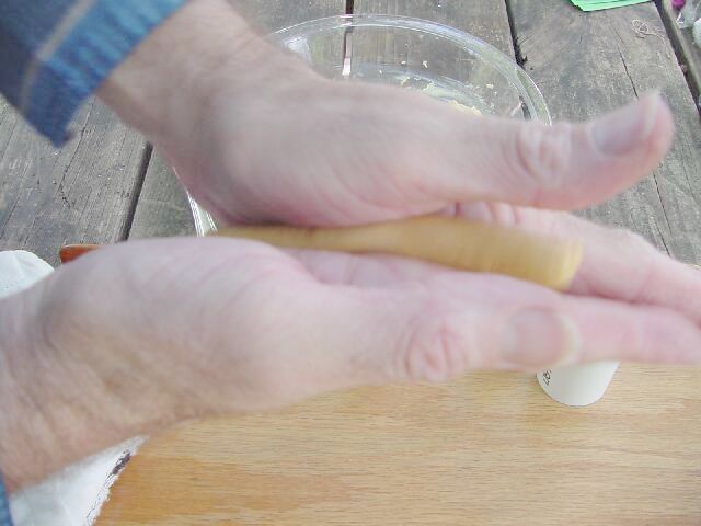


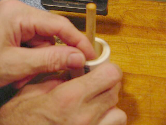
The snake-and-pack process is repeated until the mold is full. The bottom of the dowel is held centered by the plywood disk, but it is up to me and my eyeballs to center the top end. This is not very difficult, and by mashing the warm propellant back and forth can do a fair job.

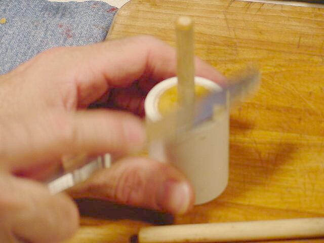
The blade of a table-knife smooths the top surface nicely.
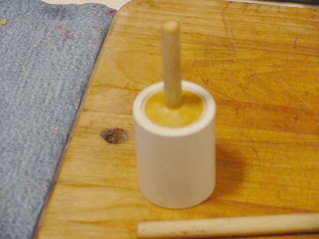
Important! Be sure to give the dowel a twist before the propellant hardens. This will loosen it and make it possible to remove later. (If it hardens completely, I just put the propellant and stick back in the oven and soften it again.)
Once the propellant has firmed up a bit, the sticks can be removed and the grains covered with a PVC cap, protecting from moisture until completely cooled. They can sit awhile this way, even longer if I put another cap on the bottom end.


Inhibiting the grains
I start by cutting a strip of poster-board paper 1-7/8 inches wide by 8 inches long. This is enough to wrap around the grain twice. One end is pre-rolled around a dowel to give it a start. A teaspoon or so of 5-minute epoxy is squeezed-out onto the strip and stirred with a stick. A propellant grain is unwrapped, a 3/8 inch dowel inserted into its core, and the bare grain itself used as a squeegee to spread the glue over the paper. This also ensures that it is spread over the propellant surface. Note that this is done on a piece of plastic-wrap to keep the epoxy off the table and off my fingers. Epoxy is one of my least favorite flavors.


Please do not be confused by the red grain slug, the overly colorful poster board, or even the purple plastic-wrap. This grain contains some red iron oxide which increases burn rate. The poster board is red on one side and green on the other. I thought the colored plastic would show up better in the photos. Please accept my apologies for not planning the color scheme any better, but Martha Stewart (R) and I have been out of touch for awhile.
For storage, the grains are wrapped in plastic-wrap and snuggled inside one of the plastic tubely cases. Each is labeled so when I use it I will know what it is.


Lead Wire
Old Ethernet cable is stripped of its outer covering and the four twisted pairs of wires removed and cut into lengths, 18 inches or longer. The pairs are separated from each other, but left twisted together. A knot is tied 4 to 6 inches from one end, the leads untwisted, and an inch of insulation stripped off. At the other end, one of the wires cut 1/2 inch shorter than the other, and 1/8 inch of insulation removed.
Bridge wire
A foot of lamp cord is cut, a knot tied in one end, and the insulation stripped from 6 or 8 inches of the other end, exposing a hundred or so very fine copper strands. One of these strands is singled out and pulled through a fold of very fine sandpaper a few times until it gleams. 320 grit wet-or-dry paper is OK, 400 grit is better, 600 is ideal. Each of these is enough for 3 or 4 ignitors.
Assembling the bridge wire
The polished thin strand is broken off the lamp cord, twisted a few times around the stripped end of the shorter wire and soldered. The strand is wrapped around the insulation of the longer lead wire until it reaches the stripped end, and then wrapped a few more times around the bare wire. It is soldered there, and the excess strand wire is clipped off. For consistency, I try to make 4 turns of strand wire on the longer lead.
Adding the pyrogen
The bridge wire is stuck on a piece of 2 inch wide masking tape about 4 inches long. A pinch of magnesium turnings is sprinkled just past the end of the bridge wire (to avoid unintended shorts) and 1/4 gram powdered homemade black powder is sprinkled over both. The tape is folded in half, sealing the powder in. Extra tape is trimmed off, the whole thing rolled into a tube, and a small piece of tape used to keep it that way.


With fresh, dry grains, the magnesium is unnecessary. But in some late-summer static tests using slightly-damp grains, black powder ignitors often failed so I started adding Mg. These enhanced ignitors have yet to fail. I like an ignitor that can burn through a thick coat of goo.
Note the skinny red stick which accompanies the wire in the first two photos. I had been using more black powder and more tape to the point that it was difficult to get it all past the nozzle and washers to the head-end of the motor. So these sticks were added to supplement the wire as a pusher, and they worked very well. Then I had an extreme spike in a static-test that was thought due the the remains of an ignitor clogging the nozzle upon ignition, and decided this was a bad idea. With Mg flakes, much less black powder is needed, so I am progressing toward Jerry Irvine's maxim that ignition should be "as hot as possible, as low pressure as possible." I will continue in that direction.
Assembly
I do not yet have photos of every little step - please refer to your Aerotech-supplied instructions for assembling the motor header, nozzle, O-rings, etc. I will show what is different about my reloads.
End-washers are made by cutting circles of automotive-type 1/16 inch "high temperature gasket material" to fit the case. One of my hole-saws is the right size, but tends to tear the material if I am not careful. Cutting them out with scissors is easy, so that is what I usually do.
Case liner is poster-board. Two layers is enough, so I cut a strip that is 1-1/2 inches shorter than the motor tube and will go around the inside of the tube twice, with a little overlap. So for the 38/360 case shown here, I cut the board 5-3/8 inches wide by 10 inches long. The grains are wrapped in this strip, and the whole thing inserted into the motor tube. (Flash Forward to 2005: I found a much better way to do this!)
So here is where I am missing some shots. I'll add these one day soon. But in the meantime, well-written instructions for installing grains, nozzles, washers, O-rings, etc. are available from the Aerotech website.

I like to seal the ignitors in with a foam ear-plug. It expands to fit the opening making an ear-tight seal, but pops out with little effort. I often find these lying about my test site, slightly scorched but often reusable.


I must have had a really good time last night...
Well no, just looking for the right screw to finish this analog test stand.

Click Here to visit the Static Tests page for these loads.
Jimmy Yawn
12/10/02
jyawn@sfcc.net