Making Grains and Assembling Motor
(Click on a small picture to view a larger version)
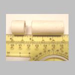
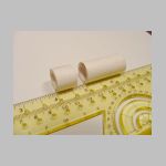
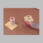
Step 1: Grain Molds
Two pieces of motor tube are cut, one 1-1/2 inches long, the other 5/8
inches long. The former is to form the propellant grain, the latter
to form the burn-through head plug, aka: "delay grain."
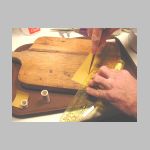
These tubes are tough, and cutting them can be a dangerous chore. I
cut these with a table saw using a plywood blade, using a section of dowel
to hold the tube and keep my fingers a respectable distance from the blade.
They were trued up on my cheesy little belt-sander. If you are not
so tool-endowed or just want an easier way, consider cutting strips the right
widths and rolling the correct length to start with. I have been doing
that since then.
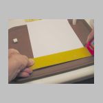
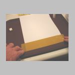
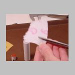
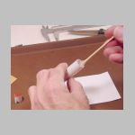
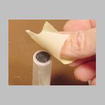
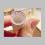
Mold liners are made by taping a strip of plastic tape onto a sheet of
typing paper, and cutting it to desired length and width. I am using
brown tape here so you can see it, but clear tape works very well too.

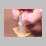
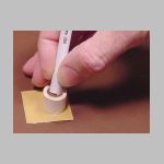
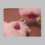
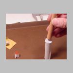
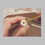
These tiny strips of paper are sometimes hard to handle with gorilla-hands
like mine. A good trick is to roll it around something smaller than
the mold, stick it in, and release it. Here, a ball-point pen serves well.
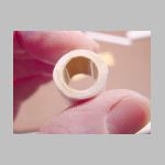
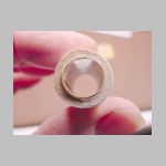
The mold liner serves several purposes: It makes the grain slightly
undersized so that it will fit in the case with a little room to spare. It
can be removed from the mold easily, and the tape covering allows it to be
peeled off without a struggle. Also, the liner can be left on the grain
or header, preventing exposure to atmospheric moisture until the next protective
operation is ready.
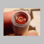
Step 2: Molding the grains
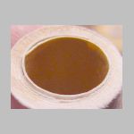
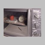
A bit of propellant has been heating in the toaster-oven at 200 degrees.
After 20 minutes or so, it is nicely soft..
DO NOT HEAT PROPELLANT IN A MICROWAVE OVEN! It will ignite!
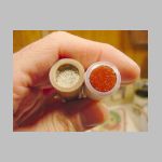
The propellant is recrystallized KN/sucrose to which 1 percent red iron
oxide (Fe2O3) has been added. This gives it a brick-red color, and increases
its burn rate. Kn/dextrose works too, and sugar syrup propellant does too,
although it burns with a little less enthusiasm.
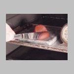
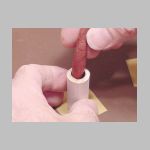
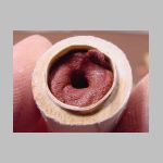
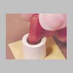
A small chunk of propellant is cut off, rolled into a slug, and pressed
into the longer molding tube with a short stick. A little more may be
added while it is still hot. The tube is filled to within about 1/8
inch of the top, and pressed down firmly.
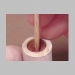
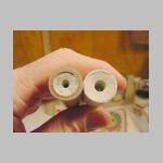
Now the 1/8 inch dowel is inserted in the middle of the new grain.
The sharp end is pushed in first, then the rod is reversed and the blunt end
is pushed through to make a full-length perforation.
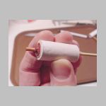
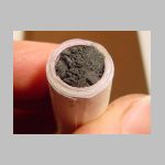
The header is made in the same manner, it is just shorter
and does not have a perforated core.
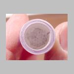
These grains will be left in the mold until the last minute to keep them
from being exposed to atmospheric moisture any more than necessary.
If you are experienced in rocket motor design you might be saying:
"Hey" you can't make the grain core smaller than the nozzle throat!
That causes erosive burning!" Well maybe so. But these work quite
well. In such a short motor with such a small grain, I don't think
it makes much difference.
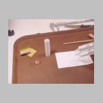
Step 3: Assembling the parts
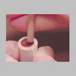
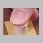
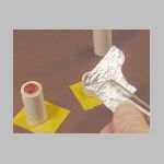
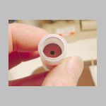
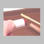
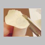
A small piece of aluminum foil is cut to form a nozzle seal. It is
roughly 5/8 inch square, and of ordinary "heavy-duty" foil. Its primary
purpose is to seal out air while the motor is stored, so the weight of the
foil is not as important as its ability to make a seal. It is pressed
into place with the nozzle rammer. Before firing, the foil will be
pierced with a pointy thing so the ignitor can be inserted.
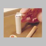
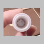
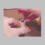
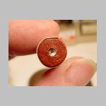
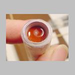
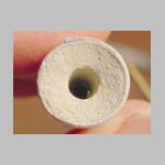
The propellant grain is removed from the mold and unwrapped.
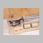
I measured it and weigh it because if it works, I may want to do it again.
If it doesn't work, I will want as many clues as I can get.
Propellant grain is inserted into motor tube. The best-centered end
down, to allow easy insertion of ignitor, and to keep the grain from blocking
the nozzle throat.
This is an uninhibited grain. Richard Nakka uses the more accurate
term "hollow core cylindrical" grains. The propellant burns from the
outside in and from the inside out. This makes for a strong, brief
thrust. Uninhibited grains ignite easily and burn with enthusiasm.
For a longer burn, consider using the Bates
grain configuration.
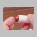
Glue in Header
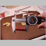
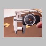
Now the length of the header grain is measured. This length will
determine the timing of parachute ejection, and so is a good thing to know.
This one is 0.626 inches long. Since this catalyzed propellant burns
at about 7 seconds per inch at 1 atmosphere, I figure this header will give
us about 4 seconds delay.
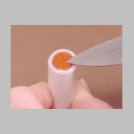
A small square of typing paper is cut and pressed down on top of the motor
grain. This is to keep epoxy from running down into the motor when
the header is installed. It is thin enough to allow the header grain
to ignite - I don't think even this small propellant grain will have any
trouble burning through a layer of paper toweling. Just don't cover
it with epoxy! *
Some 5-minute epoxy is squeezed out and stirred. 1/2 teaspoon is
usually enough.
Coat the inside of the motor tube with epoxy, being careful to avoid disturbing
the paper, or covering it except at the edges *.
|

|
Unwrap the header grain, and coat the outside of one end with epoxy.
Do not coat the flat end * as this needs to be exposed to the burning propellant
grain so it will catch fire. |
I have had exactly two header-burn failures in these motors so far, out
of about 50 tests. In both cases, the glue had oozed under the header
grain forming a solid seal, so that the header did not ignite.
|
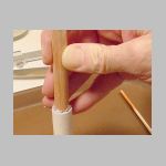
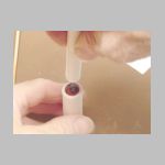
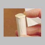
Stick the coated end into the motor case, and gob some more epoxy on the
outside. Make sure the entire outer surface of the header grain gets
coated, then gently push it inside the casing until it stops against the
paper over the propellant grain.
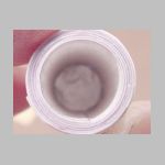
Stand the little motor upright on its nozzle, and cover the entire top end
of the header grain with epoxy. Let it set until set. It's OK
if a few drips set on the outside of the casing - these can be trimmed off
easily with a sharp knife. Just be sure the epoxy fills the gap around
the grain, and that any large bubbles are released. If this proves
overly challenging, consider using slower-setting epoxy.
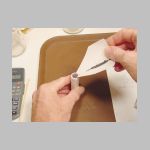
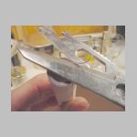
Once set, you can carve a hole in the epoxy to let the flame out.
But the epoxy has set nicely, and is quite hard at this point. Wonderful
stuff, epoxy. But it occurs to me that I have been injured a time or
two while using a sharp knife in the manner illustrated below. I need
a safer tool to do this job...
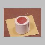
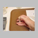
Ah! The nozzle drill! It bores a nice, round hole with little
effort and at a much lower risk of injury. I drilled until some red
stuff came off the bit, hard evidence that the propellant is exposed.
If you are making these for use later, might be better not to drill the top
hole right away. As soon as the propellant is exposed to the air it
starts gathering moisture. Eventually it is rendered non-flammable.
But since the nozzle is sealed with aluminum foil and the header is sealed
with epoxy, there is a good chance this motor could be stored for awhile and
still function. This has not yet been tested.
Ejection Charge:
0.3 gram of homebrew black powder is funneled into the end of the tube,
pressed down firmly, and covered with masking tape.
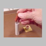
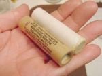
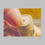
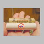
Comparison
So how does this homebuilt stack up against a commercial motor?
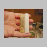
Well for one thing it is a little bit longer. This is because I let
the poster-board run of to one side while rolling the tube, and did not trim
it before use. Shame on me. For some airframes, this will make
no difference. For those using a little metal clip to hold the motor
in place, it can be a real nuisance.
Here is one that went off a bit. I will trim off the flash and check
its length. Now it's just about right.
So if your airframe requires the motor to be exactly 2.75 inches long, either
be more careful than I was in rolling the cases or trim them up after they
have dried.
Motor Specifications
Length: 2.75 inches (70mm)
Outside Diameter: 0.7 inches (18mm)
Inside Diameter: 0.5 inches (13mm)
Propellant weight: 6.9 grams
Grain type: hollow-core uninhibited
Nozzle throat: 0.1875 inches (3/16ths inch)
Initial Kn: 117 (including header, which contributes 0.196 sq. in.
burning surface)
Final Kn: 97
Initial pressure: 250 psi
Final pressure: 200 psi
Burn Time: 0.25 second
Thrust: 7.8 N-seconds (calculated, not measured)
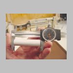
I note that the pressed Bentonite clay looks a lot like the nozzle material
on this Estes motor. I perform a sophisticated test
with to determine how solid it is. The Estes nozzle is a bit harder
than my pressed clay, but not much. I think they might add some cement.
The nozzle seal will be pierced as part of the motor prep routine, to allow
the installation of an ignitor. Here I am threatening it with a skewer.
Please note that these motors are NOT acceptable
to fly at NAR launches nor Tripoli commercial launches.
They may be acceptable at Tripoli Experimental launches, but only when made
with dextrose rcandy, not the normal version using sucrose.
Next: Ignitors, launches! (coming soon!)
Jimmy Yawn
jyawn@sfcc.net
Revised 10/10/04