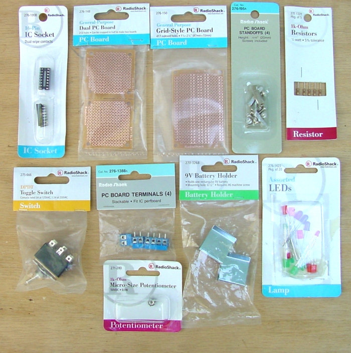
INA 125 Instrument Amplifier
for rocket motor test stand |
Board 2
A little better than the first one, I think. 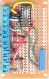
|
|
INA 125 Instrument Amplifier
for rocket motor test stand |
Board 2
A little better than the first one, I think.
|
| 1. |
|
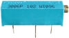
The 15-turn Cermet potentiometer is more precisely adjustable. |
| 2. |
|
It includes a resistor and terminals so that one can use a naked LED. |
| 3. |
 |
The extra elbow room makes it a little easier for a klutz like me to work on. |
| The board and its components: |
Number needed: |
Radio Shack parts number |
Price as of 10/04 |
|
| 1 |
9v Heavy-Duty battery snap connectors |
2 |
270-324 |
$2.50/pack of 5 |
| 2 |
1k Cermet potentiometer, 15 turn |
1 |
271-342 |
$2.59 |
| 3 |
Grid-Style PC Board |
1 |
276-150 |
$1.29 |
| 4 |
16-pin IC Socket |
1 |
276-1998 |
$1.29/pkg of 2 |
| 5 |
9v batteries |
2 |
2300883 |
$9.99/pkg of 4 |
| 6 |
2-Position PC Board Terminals |
6 |
276-1388 |
$2.29/pkg of 4 (get 2 pkgs) |
| 7 |
Solid core hookup wire, 22ga or so |
a foot or so, total |
276-173 |
$6.29 for 3 rolls (a bit much!) |
| 8 |
1000 ohm fixed resistor, 1/4 watt (or higher) |
1 |
271-1321 |
$0.99/ pkg of 6 |
| 9 |
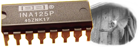
INA125P |
1 |
Digi-key INA125P-ND |
$5.10 each |
| The case and its furnishings: |
||||
| 10 |
Stranded core hookup wire, 22ga or heavier |
three or four feet |
$6.29 (this is getting absurd) |
|
| 11 |
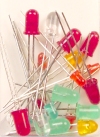
LED - 1.8v (to let us know when the amp is turned on) |
1 |
276-1622 |
$2.59/pkg of 20 |
| 12 |
DPST power switch, or DPDT switch, using only one throw.
|
1 |
275-666 |
|
| 13 |
9v Battery Holders (To keep the batteries from rattling around loose) |
2 |
270-326 |
$0.99/pkg of 2 |
| 14 |
Project Box, 6x3x2 inches (to keep everything safe and together) |
1 |
270-1805 |
$3.79 |
| 15 |
PC Board Standoffs (to hold the little board firmly in the box) |
set of 4 |
276-195 |
$1.29 |
| 16 |
RCA Jack (for connecting to Dataq unit via audio cable) |
1 |
274-346 |
$3.99 /pkg of 4 |
| 17 |
5-pin audio jack (you might use a different kind of connector) |
1 |
Not a Radio Shack part |
$1.79 at local electronics store |
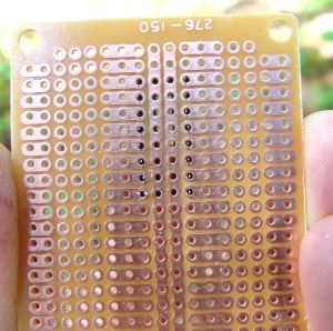
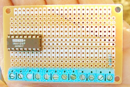
| There is an extra row of holes on the left side, offering a bit more
room. I will put the terminals and most of the wiring on this side, so things will be a little less crowded.
|
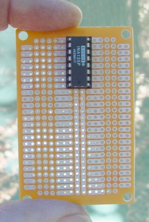
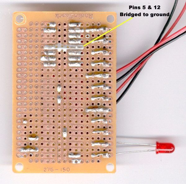
Notice how the IC socket nicely straddles ground strips running up underneath
it. This PC board layout offers lots of possibilities! | |
|
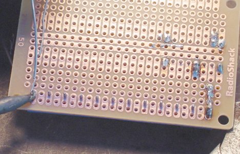
 Other side of the board. The socket is held in place digitally, no solder yet. Note that each pin has two adjacent holes connected with copper film. This makes it easy to run jumpers from any pin to anywhere else. |
|
Here the terminals and LED resistor are installed, but nothing is soldered
yet. Astute observers may note that I really need only 11 terminal connections. But these things come in pairs, and I was not interested in cutting a set in half. Aaah! The sweet Autumn scent of burning rosin! The temperature is finally tolerable here, and the mosquitoes have gone to sleep, so I can solder out at the picnic table. Some really smart guy installed a power outlet on it awhile back. Not going to name any names... |
| I had intended to show you perfectly clean, beautiful solder joints,
a delicate parabola of silvery solder sweeping up each lead and down to the copper trace in elegant symmetry. It would be a bold and compelling demonstration of my consummate mastery of the manly soldering arts, propelling me to greater success with rocketry, wealth, and women. Wishful thinking, bordering on delusional. Especially the "women" part. You get a reality show instead. I will have to settle for joints that work. Hopefully. |
|
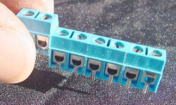
| Something else I learned after making the board illustrated below:
These terminal blocks have a dovetail spline that allows them to attach to one another, forming neat little rows. The bottom two terminals on my board are not so attached because I didn't know that at the time. I'd read it, but didn't quite realize it. Funny how that happens. |
|
They will be much neater on the next board, I promise. |
|
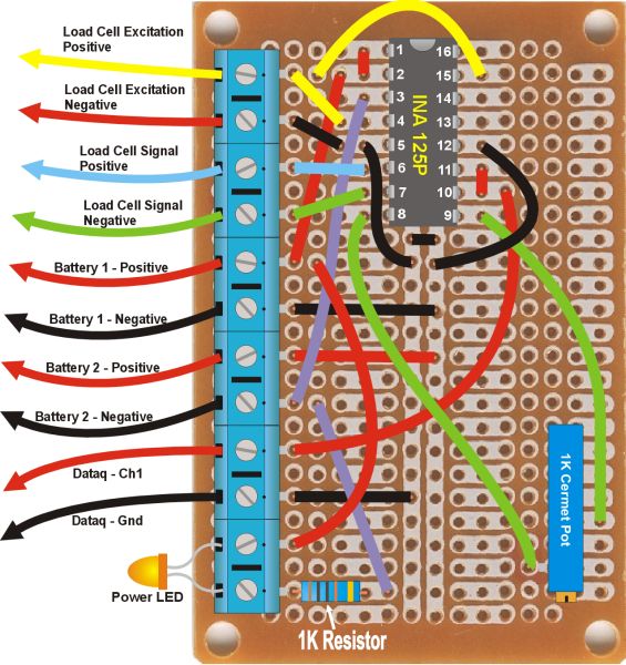
Here is a layout/wiring chart for the completed board. (Please accept my apologies if you have tried to make this amp from a previous version of this page - I had the labels for terminals 1 and 2 reversed. Terminal 1, Yellow, pins 4 and 15, is Load cell Excitation Positive Terminal 2, Red, Pins 5 and 12, (ground) is Load Cell Excitation Negative. Revised 3-7-05 |
If you build this amp, you should also have the schematic from Mike Bennett. |
 Click for larger image
|

Click for larger image |
|
Yeah, the photo is a little different from the drawing. I drew it for clarity Note that three of the black wires in the wiring chart are not necessary, and in fact are not included on the actual board. They are the wires going from pins 5 and 12 of the chip to ground, and from one side of the ground to the other. The extra wires are drawn-in to make it really clear what connects to what. In reality, I just soldered a jumper on the underside from pin 5 to pin 12 and to the ground strip as it went across. |
Next: The Box |
 |