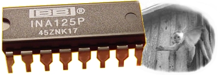
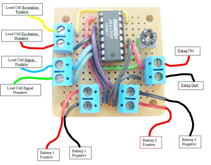
INA 125 Instrument Amplifier
for rocket motor test stand
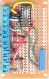
Board 1
A minimalist approach
 
Small photo of small amp board

This is my first amp.  It works.

It is built on a very small PC Board, which is 1-3/4 inches square.  This board is adequate, and I have been using it for tests lately. 
But I like the larger one much better, and if you decide to build one of these should check that model out.


The Parts
Some parts for the amplifier
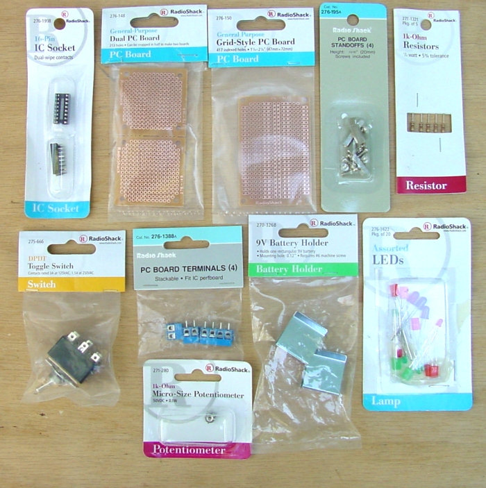
Most  parts were obtained from Shadio Rack.  Yeah, I know one gets better selection and prices from Digi-Key and other online shops, but I really don't know what I am looking for and it is a lot easier when I can pick things up, look at them and figure out how this plugs into that...

Oh, the INA125P came from Digi-Key.  To find it, do a search for INA125P-ND.  They cost me $5.10 each.  
Here is Texas Instrument's 15-page Data Sheet on this device (Acrobat .pdf file)

And the A/D converter is the 194RS Starter Kit from Dataq - a bargain at $24.95 plus shipping.


Board Components:
Number needed:
Radio Shack parts number
Price as of 10/04
1
9v Heavy-Duty battery snap connectors 
2
270-324
$2.50 (pack of 5)
2
1k micro potentiometer
1
271-280
$1.29
3
General-Purpose Dual PC Board
1
276-148
$1.79 (pkg of 2)
4
16-pin IC Socket
1
276-1998
$1.29 (pkg of 2)
5
9v alkaline batteries 
2
230-883
$9.99 (pkg of 4)
6
2-Position PC Board Terminals
5
276-1388
2.29/pkg of 4 (get 2 pkgs)
7
Solid core hookup wire, 22ga or so
a foot or so
276-173
$6.29  for 3 rolls (a bit much!)


Peripherals:


8
Stranded core hookup wire, 22ga or so
a few  feet

$6.29 (this is getting absurd)
9
Red LED assembly, built-in resistor, 12 - 16vdc 
1
276-270
$1.99
10
DPST power switch, or DPDT switch, using only one throw.  
1


11
9v Battery Holders
2
270-326
$0.99/pkg of 2
12
Project Box, 6x3x2 inches
1
270-1805
$3.79
13
PC Board Standoffs
set of 4
276-195
$1.29
14
RCA Jack
1
274-346
$3.99 pkg of 4
15
5-Pin Audio Jack
1
(not a Radio Shack part)
$1.79 at local electronics store

Total parts cost will be about $20 to $25.  But you may have to lay out a little more cash than that, getting extra parts you might not need.  

Notes on the parts:

1.  Heavy-Duty Battery Connectors.  I started out with the basic 9v battery connectors and they worked OK.  But the "Heavy-Duty" ones are easier to snap on and and off the battery.  They also seem much more durable, especially the wire leads which are thicker and clamp in the terminal blocks more easily.  I think they are worth the extra ten cents.

2.  1k potentiometer.  At first I had one of the Cermet potentiometers on this board.  It worked fine, but took up too much room.  For this little board, the dial-type pot works OK, although it is not as precisely adjustable.  It has the advantage of being adjusted from above, so that part is easy.

3.  PC Board - This board comes in Siamese pairs, which can be broken apart.  They are cheap and adequate.  If I were going into production, I might well use these, forget the large, expensive terminal blocks, and just hook the wire leads directly to the board.  Then there would be plenty of room, without those big old terminals.

4.  DIP Socket - I guess that you could solder the INA125 chip directly to the PC board, but you would need to have a light touch with the soldering iron to keep from frying it.  Steve did it, so I know it can be done.  But in the hands of a klutz like me the delicate IC could be subject to all kinds insults:  static discharges, excessive heat, physical stresses, and perhaps even some swearing while it is being soldered to the board.  So it is a great convenience to have a cheap inert socket to handle all the slings and arrows of outrageous assembly, then gently insert the delicate $5.00 IC when all the rough stuff is done.  

And suppose that it doesn't work on the first try.  (So far, exactly none of my boards have!)  I would wonder whether I killed the IC during the assembly process, and add that doubt to my list of trouble-shooting options.  To test that hypothesis, I would have to de-solder that IC and solder-in another one, possibly frying it too. For me, the IC socket is worth its cost several times over.  

Note that since this piece of hardware does not go in the airframe, it does not need to be flight-ready.  If this were an altimeter, I would wonder about the holding strength of the socket, and likely build it stronger.

5.  Batteries.  I suppose this project could be made to run from a transformer converting 110VAC to 9VDC, but have heard that one must then take precautions about filtering the resulting current for AC artifacts.  Here I am going with batteries for the sake of simplicity, portability, and the fact that I have no clue as to how to filter current appropriately.   The set of alkaline batteries Steve provided with the amplifier several months ago are still serving well, despite me roasting them with a bad hookup the first time testing my little amp - they got hot!  Despite this trauma, they still work fine.  If one does a lot of such testing, perhaps rechargeable batteries would be cost-effective.

6.  I like terminals, and like to use them for every wire that leads off the board.  First off, they are cute.  Secondly, they offer options.  

These terminals may be unnecessary in a "production" version of the board, once the design of the whole test system is finalized.  That means that you know what kind of connectors you will use for the load cell and the A/D unit, what kind of box it will go in, and have tested things well enough to be sure it is right the first time, or at most the second time.  And since the terminals take up a lot of room on the board, doing away with them would make working with the smaller board much easier.

But the terminals let me disconnect leads at will and reconnect in different ways to test things out.  This is good, in that I made several wiring errors on the first try.  Had the wires been soldered in, it would have taken a lot more time to troubleshoot.  

These terminals are kinda hard to find locally.  That's because whenever I see them in a store, I buy them all!  Radio Shack only stocks a few at any given time.  I have gone to every store in town and cleaned them out. Next time I order from Digi-Key, I will get a large bag of terminals!

7 & 8 - The Wire.  One could probably get away with either solid or stranded wire but it is better to have both.  Solid wire is much easier and cleaner to work with on the PC board, as it bends to shape easily and solders cleanly.  But solid wire fatigues and breaks if subjected to repeated stress, causing "flaky" connections.  So stranded wire is better for leads that will be exposed to handling in the finished product - anything that goes off the board or especially outside the box.

Stranded wire can be used on the PC board, but it doesn't stay bent very well, making it harder to route cleanly from one spot to the other.  Also the little strands may break loose from the pack to become "wild hairs" that short to adjacent connections.  They are hard to see.

But if given a choice of one or the other, I would use stranded wire, and be really careful about soldering, trimming, and cleaning up afterwards.  Care and persistence in wiring the board will be rewarded with more reliable connections.  

9.  The power-on LED is a really good idea, so that you know when the unit is turned on or off.  This can save some doubt when trouble-shooting
(Hey...no data.  Did I forget to turn the darned amp on again?) And as Terry McCreary observes, a power-on LED can save a lot of batteries.

Pictures
(Click on a small picture to view a larger image.)

Here is a wiring chart which shows how the lead wires are hooked into the little amplifier:

Small Amplifier Board Drawing
Here is a photo of the finished board:

Small amp board, photo
If you build this amp, you should also have the schematic from Mike Bennett  (Acrobat .pdf File)

INA 125 Schematic
His wire colors are not the same as mine, as he is using a different load cell

Also note that  a few of the wire connections are not apparent in the photo, as they are on the other side of the board.  They are drawn in the drawing to make it clear which objects are connected.  For instance, pins 1 and 2 are connected by a solder bridge on the reverse.  So are pins 10 and 11.  


Next:  A Better Board
Well that was fun.  It is even proving useful.  But will I stop there, Noooo!  
There are more boards to build, more elegant designs....
Here is a step in that direction.
  Board 2, small photo

Jimmy Yawn
jyawn@sfcc.net
rev. 12/8/04