I first learned about static tests from B. R. Brinley's book: Rocket Manual for Amateurs which was in my high school library. What a waste! Taking a perfectly good rocket motor, strapping it down, and firing it so it can't go anywhere. Why not let it fly and see how far it goes?
Well that was a fine adolescence, and I have since learned to appreciate both test stands and sandbag bunkers. Problem is, at the advanced age of 51 I still did not have a test stand.
But I had thought about it. A lot. At one time I had planned to make an analog test stand using a leaf-spring of aluminum, securing one end, placing the motor at the other, and having a pencil attached to the spring draw on a rotating drum as the rocket motor burned. I never quite figured out how to build the rotating drum.
When in my 30's an engineering student showed me a catalog photo of "rosebud" strain gages, I got excited. By then I had a Commodore 64 and had learned to program fast routines in 6502 assembler, controlled by nice user interfaces written in Basic. I made a chronograph for recording the velocity of my firearms, but ran into trouble. It was difficult to break two wires strung 10 feet apart with one shot. Got it to work a time or two with a shotgun, but it wasn't much fun and was soon abandoned.
Last year someone on aRocket mentioned using a video camera to record the readings of a pressure-gage during a static test. A little later Jerry Irvine suggested recording the readings on a baby scale as a low-tech thrust gage.
In my first static tests of KN/SU reloads in Dr. Rocket cases, I noticed that the 2x10 board supporting the motor flexed noticeably during thrust.
I already owned a digital camera capable of making short movies.
Finally, all the pieces had fallen into place. I just needed to make a calibrated spring-arm for my motors, and record the tests on video.
So here is the first one.
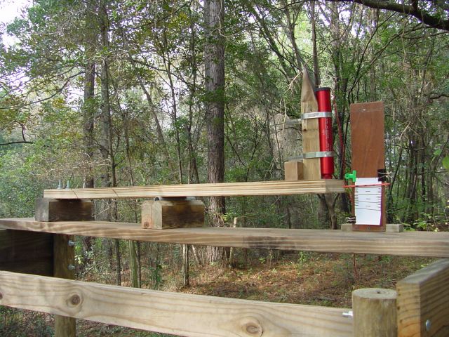
Test Stand A
It is rigged up as a temporary to see how the concept would work in
practice. It worked pretty well, despite its jerry-rigged construction
and very coarse scale. The beam is one thickness of 3/4 inch hardwood
plywood, cut 5 inches wide. The scale was drawn by stacking bricks
and blocks of known weight on the motor-holder, and drawing a line where
the pointer pointed. The brown thing on the right brick is a piece
of railroad iron, with a little ridge toward the right side. This
serves as a fulcrum, at which point the board is bent.
Video of 9/8/02c - 38/360 case with 3 Bates
grains, slightly regressive burn (500k file, 3 seconds of video)
Excel spreadsheet file analyzing this test
One of my more radical tests bottomed-out this stand, So I decided to make a stronger, more permanent version
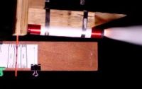
Test Stand B
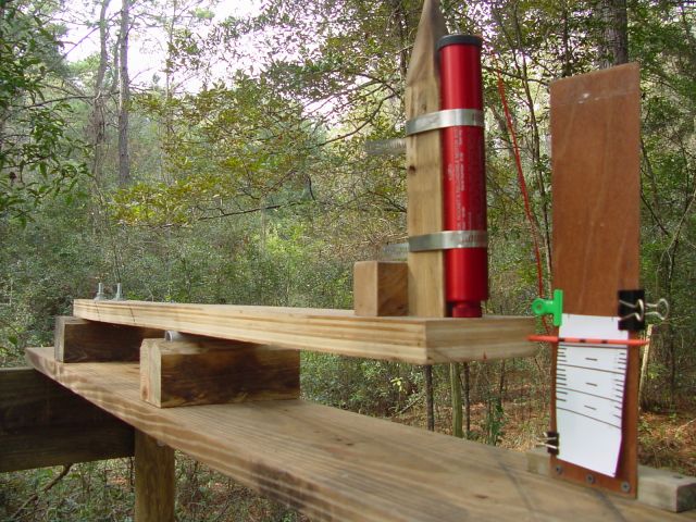
The beam is two thicknesses of 3/4 inch hardwood plywood glued together and trimmed to 5-inch width. It is attached at the far end with 8-inch carriage bolts, spaced with a short section of 4x4. The fulcrum is an aluminum tube, positioned halfway between the bolts and the head of the motor. The fulcrum mounting block is secured with a few screws so that it will stay put for now, but can be moved without a lot of trouble. This is to allow the stand to be adjusted to accommodate larger, stronger motors.
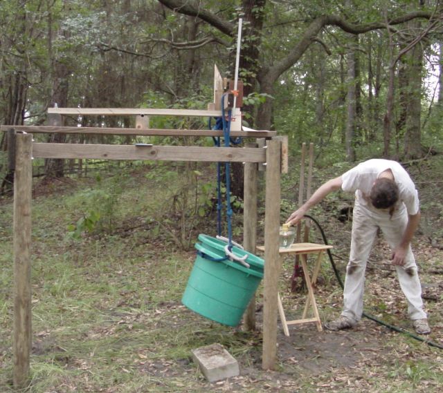
The first calibration was done by clamping a short length of 2x4 just in front of the motor-mount, looping a rope over either end, and slinging a large bucket underneath. 10 liters of water was measured out and poured in the bucket, and a line drawn at the level of the pointer. Another 10 liters added, another line drawn, etc. Thus each line should represent 10kg of pressure. Oh yes, the board, rope, and buckets were weighed and supplemented with bricks and stones to make the first 10kg.
This calibration proved to be faulty. I was getting ISPs in the 200s with KN/sucrose. While this did wonders for my ego, thinking I had developed a "super candy" propellant, this little voice kept telling me it was in error.
So a second calibration was made using a suspended platform and weighed bricks. This one seems more accurate, giving readings within the realm of possibility.
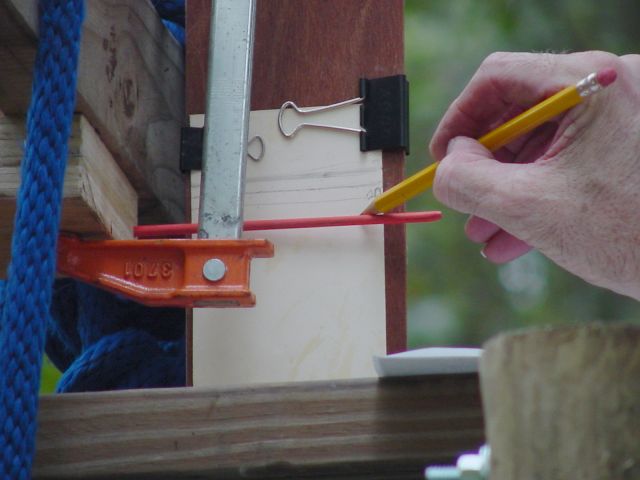
The scale is held on with paper clamps, making it easy to move and remove. In fact, I have scanned it and made a nicer-looking version that has not yet been rained-upon like this one has. I bent a piece of tin down the middle to make a removable tin roof for this stand. Then I forgot and left it off during a rainstorm. Twice. Oh well. You don't have to be stupid to do dumb things. I will let it dry out awhile and re-calibrate it again.
And that cute little point at the top of the motor-mount sticks nicely into a groove in the tin roof, holding it steady. The wood of that stand was slavaged from my first 4x4 airframe, which was rapidly reconfigured by a pvc-motor CATO last December. The point was part of the pyramidal nose "cone."
Here is a sample video. The motor is a Dr. Rocket 38/480 casing firing four KN/sucrose grains totaling about 200 grams propellant.
(Click here to download this movie -
820k file, 5 seconds of video)
No, I did not turn the test stand on end, I turned the camera sideways in order to get the best view of both the pointer and the exhaust plume. "Up" is to the right. Center of the Earth is to the left.
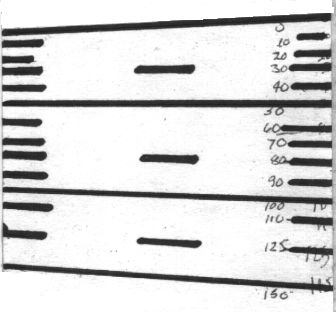
Below are thrust curves produced by analysis of the video.
My video camera does an annoying thing: It skips every third frame when making movies. So even though the movie plays at 24 frames per second, I only get 16 measurements. Each skipped frame is an exact duplicate of the one right before it. This makes the movie appear to run smoother, but creates some odd little bumps in my thrust-curves.
The second curve has been smoothed by eliminating the values of duplicate frames.
(Click here to download the Excel spreadsheet
generating this graph - 21k)
In watching the videos, it is apparent that the 2 x 10 base under the spring-beam flexes a lot, perhaps as much as the beam itself. I assume this to be of no great consequence as long as it is mounted on the frame in the same position each time.
Conclusions
Is this the ultimate in test stands? Hah!
Is it accurate? Not likely.
Is it consistent? Questionable.
Does it look like a high school science fair project?
Yes. And of this I am proud. I have been thinking about
this since I was 15, finally built it at age 51.
I am looking forward to having a better test stand, and plans are a-brewing. But for the moment, this gives me more data than I have obtained from any previous test methodology. Here is my chronology:
Age 14 - 50: Strap it to a stick and watch it go.
Age 50: Strap it to a fence post and observe the smoke, noise,
and remnants.
Age 50.5: Put it in a heavy airframe, track its flight, and get
a rough estimate of thrust and ISP.
Age 51: Strap it to a dorky test stand and get a rough thrust-curve
on video.
Age 52 (I hope!) Put it in a streamlined airframe with an altimeter,
and watch it go.
Eventually: Put it on a good digital test-stand and determine
whether the current method is accurate at all.
******************************************************************************************
Back to Recrystallized Rocketry home page
Jimmy Yawn
jyawn@sfcc.net
11/23/02